Basic design
PolyBoard Essentials: Previous | Next
- Cabinet design video introduction
- Free vs full version of the software
- Create a new cabinet (Cabinet mode)
- Angle of view
- Positioning your design in the edit window
- 3D view
- Basic selection and editing
- Properties menu
- Resize cabinet
- Add design elements
Cabinet design video introduction
This video shows you how quick and easy it is to set up a cabinet, edit it, view in 3D and output the cutting list, plans and CNC files.
Feel free to follow the video and set up your own cabinet then continue with this guide to go through each step in more detail.
Free vs full version of the software
If you’re using the free version of PolyBoard, 100% of the design features are enabled, but you won’t be able to access the manufacturing output. However, any designs you create with the free version can be used with the fully activated software.
Lots more detail on the output options follows, sample output is also available on the download page.
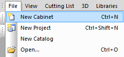
Create a new cabinet (Cabinet mode)
We are working here in Cabinet mode, in which you design a single cabinet.
Select File menu > New cabinet
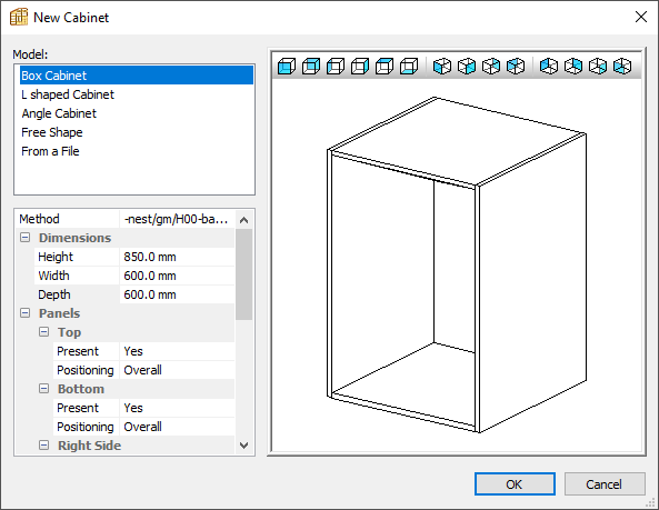
In the New Cabinet dialogue box, choose from these 5 options (the box cabinet is a good place to start):
- Box cabinet
- L shaped cabinet
- Angle (or corner) cabinet
- Free shape (ability to define highly complex shapes)
- Import from a file (import a DXF files of the plan view)
You can also specify now or later:
- Manufacturing method (your manufacturing preferences, more to follow)
- Dimensions
- Panels section to determine whether to include specific parts or not
For now just select the default manufacturing method, we’re just going to focus on the main design commands rather than the details of the hardware and your other construction preferences.
Click OK and your basic box cabinet will be created.
Angle of view
You can change the angle of view in the New Cabinet window, or later in the Quick Design View toolbar.
Alternatively, go to:
View menu > View Angle (➦ shortcut: V)
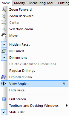
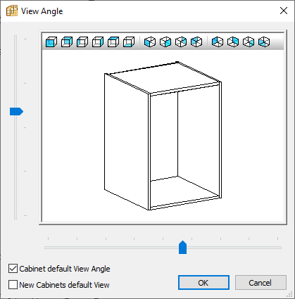
Here you can:
- Select a predefined angle
- Drag the image to suit your preference
- Set a default view
Positioning your design in the edit window
If your design isn’t positioned in the window as you want it, right click outside the cabinet and select Move, then click and drag with the mouse (➦ shortcut: depress mouse scroll wheel and drag).
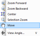
Right click > Quit move when finished
In the same menu you can zoom (➦ shortcut: mouse wheel) and centre your design.
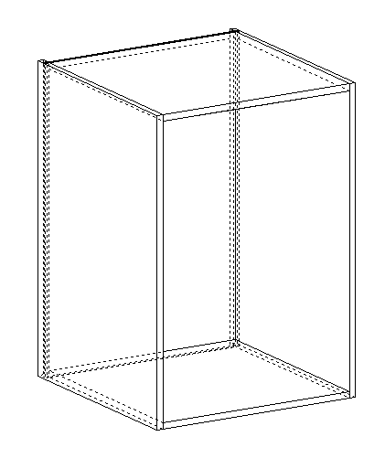
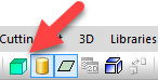
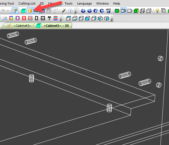
3D view
PolyBoard offers instant access to your design in 3D as you edit it. This is great for customer presentations, and to assess your design concept and aesthetics.
The green cube icon opens the 3D view.
There are a range of 3D view options available as shown below:

The most commonly used options are:
- Solid view (green box on the left)
- Hidden faces wireframe view (selected)
- Open, close and hide doors and drawers (cabinet icon)
- Show/hide shadows (last icon on the right)
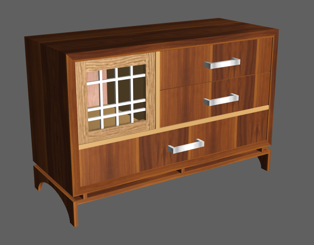
Here’s a cabinet shown in 3D solid view:
To show/hide hardware machining details (visible in Cabinet mode only), select this icon:
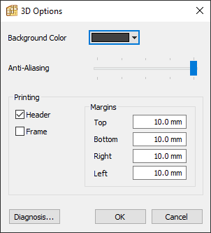
Finally, if you want to change the background colour, go to:
3D menu > Options > Background colour
★ Tip ★
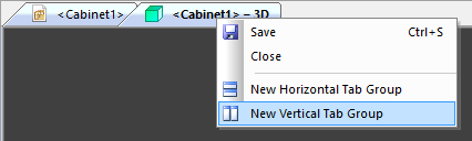
Right click on the 3D tab and select ‘New vertical tab group’ to see the edit and 3D windows next to each other.
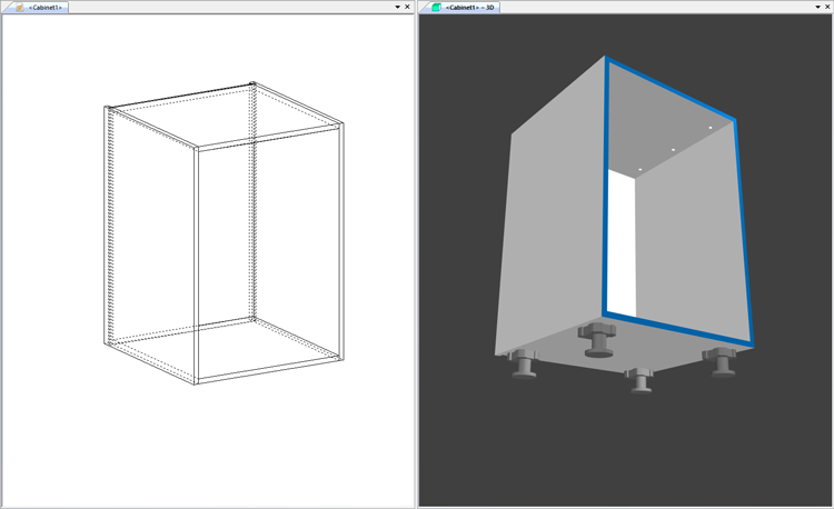
You can switch between the edit and 3D windows using this icon:
★ Tip ★
The full version of PolyBoard includes a 3D view print option, we also recommend any good screen capture application (many are free) to copy any angle or part of the design as required.
Basic selection and editing
To modify your design, you need first to select one of:
The whole cabinet
Just click outside the cabinet.
A specific part
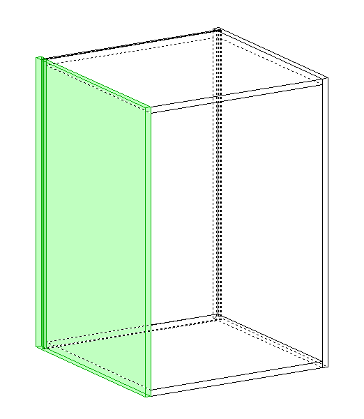
Click on the part, when selected it will go green.
★ Tip ★
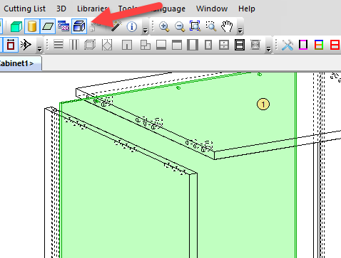
To select the part you want, it sometimes helps to click on the edge of a part or to explode the parts first.
★ Tip ★
To select the part in the foreground, hold down the Shift key.
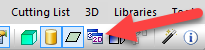
You can also select a part from the drop down menu at the top of the Properties menu:
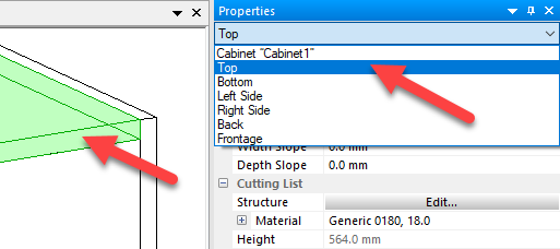
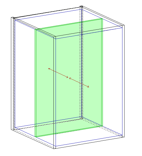
An internal or external volume
Click on the volume or space, when selected it will go blue.
This video provides more detail on how to make selections:
Properties menu
Once you’ve made a selection, the Properties menu is where you edit your design.
Edit entire cabinet
With no part selected (click outside the cabinet) to:
- Adjust overall cabinet dimensions
- Add external zones to allow application of plinths, upper strips etc.
- Add or remove specific parts
Edit a specific part
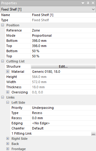
With a part selected, this menu allows you to modify the following:
- Position (of internal parts), is defined proportionally within a volume or as a fixed distance from an adjacent panel
- Cutting list to define the material and access additional panel design features in the Structures menu
- Links (the connection between a part and any neighbour) to define which has priority (which is overpassing vs underpassing), add grooves, tenon and mortise and other joints, and offer one way to apply hardware and edging
★ Tip ★
If the Properties menu is hidden, activate it again here:
View > Toolbars and Docking Windows > Properties (➦ shortcut: Alt + Enter)
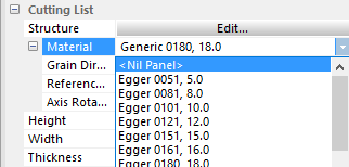
Cutting list part dimensions are not editable!
In the full version of PolyBoard the cutting list section of the Properties menu shows the dimensions of each part, see the image above.
However, in the free/demo version, these values are replaced by the word Demo.
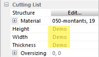
That’s because the free version does not show the manufacturing details.
However these part dimensions are for information only, they are not editable.
To confirm, ALL design features are available in the free version, you adjust your design dimensions elsewhere, read on for details.
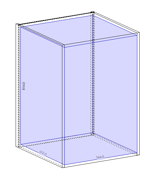
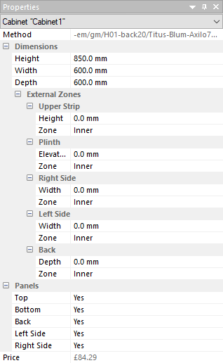
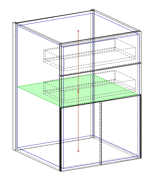
Resize cabinet
With the whole cabinet selected, you can edit the global outer cabinet dimensions in the Properties menu as shown below:
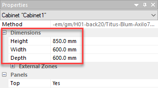
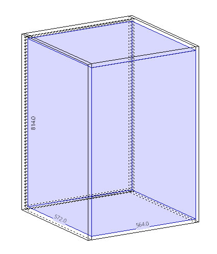
If you select an inner volume, the Properties menu will display the inner dimensions of that space and can be edited in the same way.
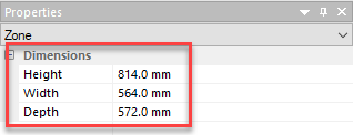
These inner dimensions can be shown in the editing window, to turn them on and off go to:
View menu > Dimensions
Cabinet wide design edits in seconds
Once you’ve added your doors, drawers, shelves etc, you can simply resize the entire cabinet and all parts will resize automatically, and all manufacturing output is updated in real-time too.
More on adding these elements coming up next…
Add design elements
PolyBoard’s design workflow is intuitive, it reflects a real-life design process where you create your carcass and simply add the drawers you want, the doors, the shelves and uprights, plinths and upper strip. You can move these, delete and replace them, change the material and so on very quickly.
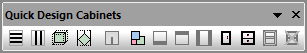
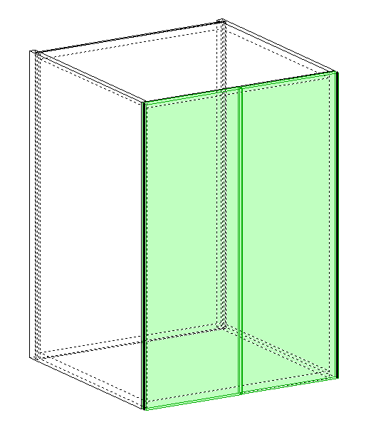
To add these components, you need to first decide where to place them by selecting an inner volume, which will turn blue.
Then click on the design component in the toolbar:
Alternatively right-click on the volume to display your options:
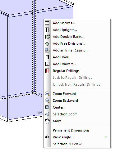
Or to go:
Modify menu > Add divisions
An element that for technical reasons cannot be added will remain greyed out in the menu or toolbar.
Once you’ve made your choice, an additional properties window is displayed. Many of the parameters you set here can be edited later via the Properties menu.
Shelves and uprights
These are simple interior elements which can be added singly or as a group.
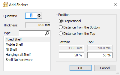
Properties include:
- Quantity
- Position, whether a fixed distance or proportional
- Type
- Thickness (editable in the Materials library, not here)
Type is fully configurable but our selection includes:
- Mobile and fixed shelves to allow specific hardware to be linked to each
- Nil panels, see below
- No hardware panel where no fittings have been linked
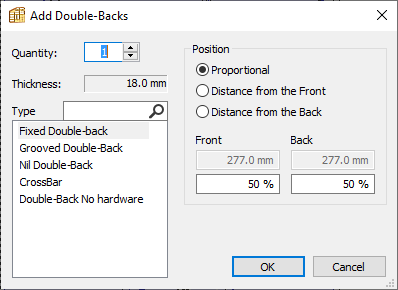
Double back
An additional panel parallel to the back that can be set at any distance from front to back.
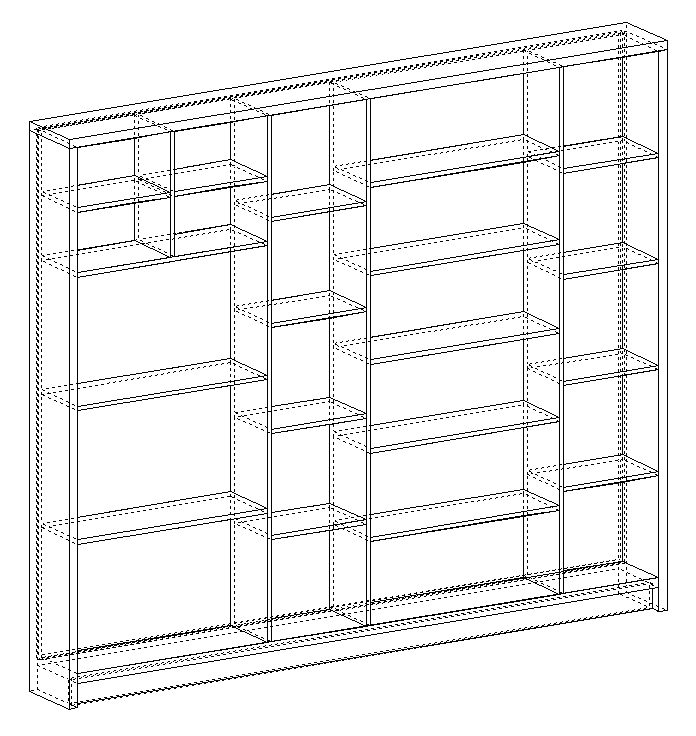
Nil panels
A nil panel is a virtual panel used to divide a volume where you don’t want to add a real panel.
It is a useful way to manage the internal space of a cabinet, for example, to add drawers above doors where you don’t want to have a separating shelf:
Ways to create a nil panel:
- Select the panel type nil option when adding the part
- Select the part > Modify menu > Nil panel
- Select the part > Properties menu > cutting list section > change material to Nil Panel (see image below)
To turn the display of these nil panels on and off, go to:
View menu > Nil panels
Doors
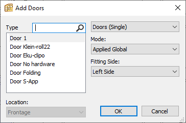
Door properties allow you to define:
- Single, double or sliding
- Fitting side (which side it opens from, top and bottom opening too)
- Typically built-in or applied global (overlapping the front of the cabinet), applied local is another very specific option where only adjacent panels move back to allow the overlap
- Type, including some doors set up for specific hardware
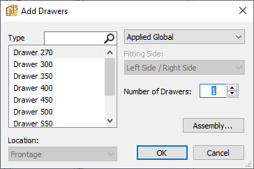
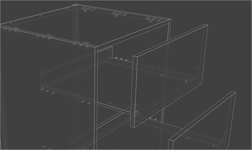
Drawers
These more complex components have internal elements and façades.
Drawer properties include:
- Quantity
- Built-in, applied global or applied local
- Types which here relates to the depth
- Assembly, an additional properties window
The Assembly properties include a further range of drawer configurations to customise the set-up to a very fine degree.
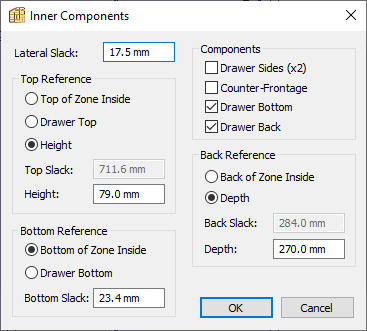
Options include:
- Include or exclude components: sides, counter frontage, bottom and back
- Lateral slack between drawer and side panels
- Depth or back slack in relation to the panel behind the drawer
- Bottom slack to the panel below drawer
Drawer façade management
With the drawers selected a further set of parameters can be adjusted in the Properties menu:
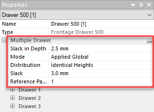
The key options are:
- Slack in-depth, from the façades to the cabinet front
- Slack, between each drawer façade vertically
Select the 3 dot icon to access the Multiple drawer window:
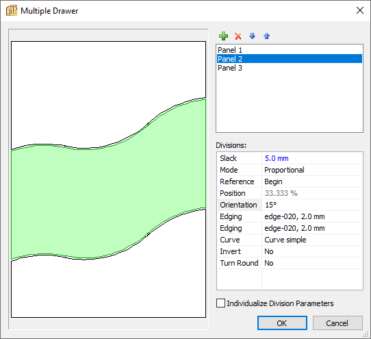
Options here include:
- Adjusting slack again
- Adding and editing a shape to the division between each façade
- Applying edging
- Select Individualize division parameters to go one step further and edit individual façades rather than all of them at once
Please note that some of these changes, in particular choosing curved façades, won’t be possible if your drawer has internal components.
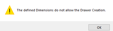
If the design (or chosen drawer size for example) conflicts with the available space PolyBoard will issue a warning message:
Traditional vs pre-manufactured drawers
Both traditional and pre-manufactured drawers by Blum, Hettich etc can be managed in PolyBoard. You can include all parts of a drawer in your cutting list, plans and CNC files, or just the elements not already supplied by the manufacturer.
And all the hardware – the drillings for the drawer sliders and the panel fittings for all parts – are automatically applied and included in the manufacturing output.
Both doors and drawers have their own manufacturing sub-method where you can set up your preferences and apply them with the click of a button. There’s no need to set up your specific configurations each time.
Once you’ve set up your preferences, all you really need to do is add the number of drawers you want and the type and the rest is taken care of.
Manufacturing methods are covered later.
More details:
Extended: Quick Design libraries
Plinths, upper strips, fillers and more
PolyBoard also offers the ability to add external zones, outside the cabinet carcass.
With the entire cabinet selected, open the external zones section.
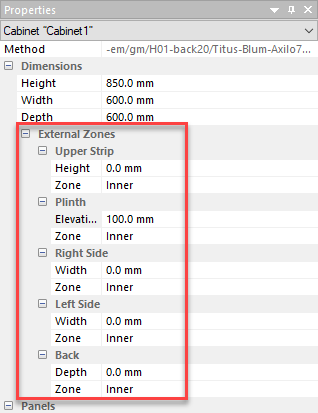
Once you’ve added a dimension to any of these zones, click on the new zone in the cabinet edit window.
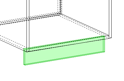
It will turn red and you can then add a plinth, upper strip or filler to the side for example.
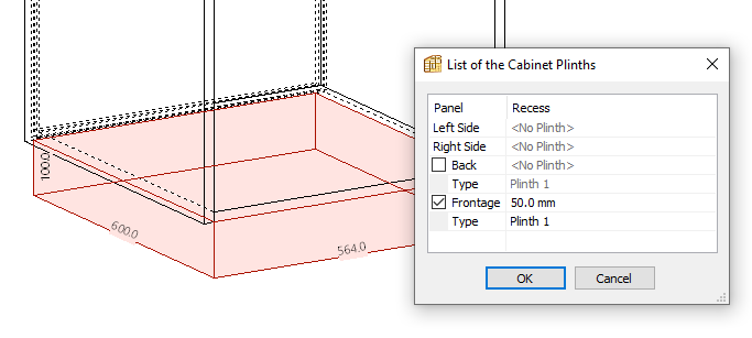
You won’t be able to add a plinth to the sides unless the bottom panel is overpassing the side panels.
This video shows you how to add a plinth and how to adjust some of its parameters.
Other uses of external zones include adding shelves to a side zone, or creating a thin zone at the back and adding a shelf to act as a hanging baton.